Cable sheath testing
Sheath fault location with BAUR

Damage to the cable sheath can lead to cable failure within a few years. It is therefore crucial that cable sheath faults are detected, located, and rectified at an early stage.
If an elevated leakage current, indicating a cable sheath fault, is detected during testing the fault should be rectified as quickly as possible. The reflection measurement technique is unsuitable for locating cable sheath faults or faults due to earth contact, as the ground does not represent a usable return phase in such fault types.
Bridge measurement methods are particularly suitable for pre-locating cable sheath faults. They are based on the ratio method in which the resistance is determined before and after the fault location. This pre-location is performed by applying DC voltage to a cable route that has been disconnected from the network.
The BAUR shirla allows bridge measurements to be performed according to the Murray or Glaser principle. Both principles are based on the Wheatstone bridge circuit, in which the two points in the measuring circuit are balanced to the same potential so that a measuring unit (previously a galvanometer) connected between these points does not display any current. The bridge circuit is then in equilibrium.
The measurements themselves are performed fully automatically by the BAUR shirla. The operator needs only enter the maximum voltage, length, material and cross-sections of known sections and connect the test cables to the test object. After the measurement has been completed, the fault distance is shown on the display.

shirla
Portable device for cable sheath testing
Murray measuring bridge method
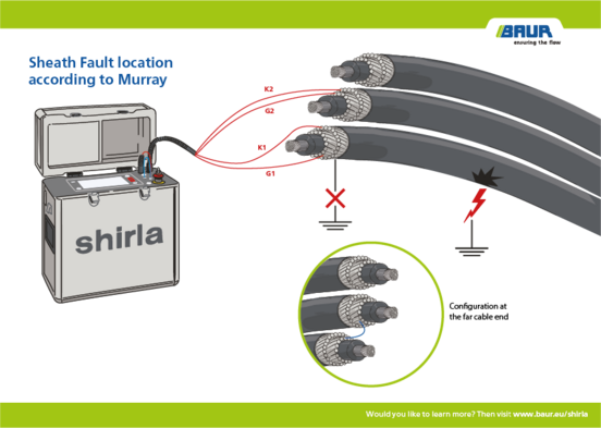
Bridge measurement according to Murray can be used for low- and high-resistive faults. The Murray method can be used when, in addition to a faulty phase, another similar and undamaged phase is available.
The bridge is connected and the faulty phase is short-circuited with the healthy phase at the far end of the cable. To ensure a high level of measurement accuracy, the resistance of this connection should be as low as possible.
If there is a cable sheath fault, a current flows that brings the balanced measuring bridge out of equilibrium; this can be brought back to zero by adjusting the potentiometer. A prerequisite for this calculation is that the conductor cross-section and materials are constant along the entire cable route.
The Murray measuring bridge method can also be used if the conductor cross-section is not constant along the cable route. In this case, the parameters of the sub-sections in question must be entered before the measurement is performed. The device calculates the fault location automatically based upon this information.
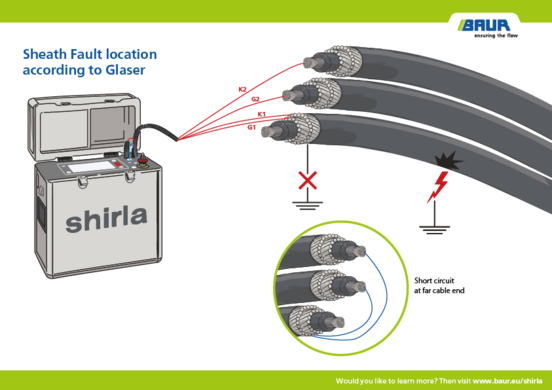
Glaser measuring bridge method
If there are at least two undamaged cores available in a screened cable that can act as auxiliary lines, the Glaser measuring bridge can be used. In this arrangement, the two auxiliary lines are connected to the defective core. The advantage of this is that the use of two auxiliary lines gives rise to compensation, and the remaining external electric circuit can be clearly assigned to the fault.
The pre-location described above determines the distance from the fault. However, since an underground cable is never straight, the fault position is only ever known approximately. Even with a measuring pre-location accuracy of 0.1% and above, the difference that can be expected from the actual geographic position is up to ±10%. For a 1 km long cable, this could represent a possible fault position within a range of 200 m.
Pin-pointing serves to eliminate this lack of accuracy using measuring technology, and to reduce the amount of excavation work required to a minimum. To this end, a pulsed DC voltage is fed into the faulty screen and the voltage then measured on site with a special voltmeter using earth spikes as measuring electrodes. The pulsing improves recognition of the signal, but also eliminates faults due to galvanic effects or other voltages in the ground.
Among other things, the protrac® pin-pointing system is used for the precise pin-pointing of cable and cable sheath faults. Thanks to the use of the latest technologies, locating the exact fault position with the protrac® is extremely fast and precise. The innovative two-level signal processing concept permits a high degree of sensitivity and accuracy, and maximum suppression of ambient noise.
When pin-pointing with the protrac®, the step voltage probes (SVP) are used in conjunction with the CU control unit and a HV source to locate cable sheath faults.
The principle of pin-pointing is simple: the deflection of the voltmeter points towards the fault and the measured voltage increases steadily as the fault is approached. Shortly before the fault location is reached the voltage rises sharply and then falls to zero as soon as the earth spikes are inserted symmetrically to either side of the fault. The precise position of the cable sheath fault is thus located.

protrac® “Step voltage” set
Sheath fault location with step voltage
Case study of an HVDC cable
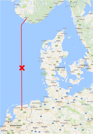
Sheath fault location with a measuring bridge is suitable for a diverse range of cables. It is even possible to measure cables hundreds of kilometres long, which is what took place on the 450 kV HVDC connection between Norway and the Netherlands.
A cable sheath fault was successfully located on the 580 km long cable route using a BAUR device and the Murray bridge measurement method.
The cable sheath fault was measured approximately level with Esbjerg. The relatively accurate pre-location of the fault along the 580 km long submarine cable simplified and sped up the fault pin-pointing process.
Overview of cable fault location
Back to the cable fault location process
Product overview