Passive and active tracing
Cable fault pin-pointing method

In the case of newly installed cables, detailed data is often available, for example in a Geographical Information System (GIS). If this is not the case, tracing must be performed with suitable devices. There are two methods available for this:
Passive tracing
There are two approaches to the passive method: Tracing with mains frequency or with radio frequency.
These applications are options if the cable is not directly accessible and cannot easily be disconnected, or simply if it is necessary to find out whether there are cables in the excavation area before work commences.
If the cable is live, the 50 Hz mains frequency can always be used as a signal. Radio waves can also be used for simple tracing.
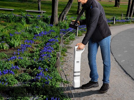
All these frequencies generate a magnetic field around the cable, which can be inductively received and traced using a receiver coil that the measurement engineer guides over the ground.
As nearly all underground conductors, including water pipes, emit 50 Hz or radio frequency signals, this method always works, although with the limitation that it is not possible to work selectively. It is not possible to definitively classify a conductor, because every metallic conductor in the ground emits these signals.
Active tracing
If selective tracing of a specific phase is necessary, active tracing is the only option. In this method, a defined frequency is fed into the cable and then located and traced at the surface.
For active tracing, the cable is first de-energised and, ideally, earthed at the far end of the phase. It is then connected to the signal of an audio frequency transmitter. There are basically three options for this:
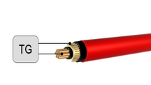
- Galvanic coupling with direct connection to a functional phase
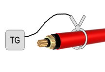
- Inductive coupling of the audio signal via a signal injector that surrounds the cable end
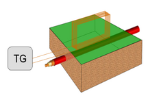
- Inductive coupling using a loop antenna
The correct coupling for active tracing
Signal coupling with the transmitting clamp can be used even if the cable is in operation, e.g. if the position of spur lines and joints needs to be established for service lines. In this case, the mains frequency and the coupled signal are superimposed.

Using the loop antenna, signal coupling is also possible if the cable is not directly accessible, for example because it is buried at the coupling point. However, this gives rise to the problem that the loop antenna signal is coupled to the receiver through the air alone at distances from 5 to 10 m.

Whereas, with galvanic coupling, the full power of the audio frequency transmitter can be fed into the cable, with inductive coupling, only a small percentage of the available energy ends up in the cable. If the cable is in operation – and thus not earthed – the traceable distance is reduced to a few hundred metres, because if no return phase is available the fed-in frequency only propagates due to the cable capacitance, and the signal strength decays exponentially with increasing distance.

The correct frequency for active tracing
The following basic rules apply:
- Low frequencies have a greater range and are less likely to inadvertently couple to nearby cables, but have a poor transmission quality when using inductive coupling methods.
- High frequencies suffer from higher levels of damping, have less range, and couple very easily to nearby cables, making them less isolated. They exhibit better transmission quality with inductive coupling.
The optimal selection of frequency and transmission power is always a compromise and it is entirely possible for this to change during tracing.
Less is more: The less transmission energy used, the fewer faults can be expected.